|
| |
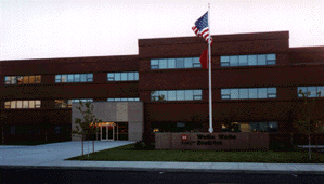
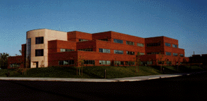
Walla Walla District Office Installed: 1994
Building Size: 95,000
Number of Units: 117
 |
| The Walla Walla District office is closely related to the development of the water
resource projects on the Columbia and Snake rivers. First established in 1948 the office
now covers approximately 115,000 square miles in six states including: Washington, Oregon,
Idaho, Wyoming, and small parts of Nevada and Utah. The District personal strength is
approximately 700 employees. About 400 of them work at the district office in Walla Walla
which manages several activities including Emergency flood assistance, regulatory
functions governing activities that effect the regions water and wetlands. The office also
manages wildlife habitat areas and recreation facilities at eight Corps projects. Since
1968 the District office has been managing a juvenile fish transportation's program which
uses specially equipped barges and tanker trucks to carry migrating salmon and steel head
fingerlings around dams on their way down the Snake and Columbia river. In the process the
district has also built several fish hatcheries. When building these hatcheries the
engineers decided to utilize the massive amount of water flowing through the tanks for
heating and cooling, they accomplished this by installing water to air heat pumps. After
experiencing the overwhelming energy efficiencies of these units, the Corp decided to use
them on their new district office in Walla Walla.
The city of Walla Walla had a parcel of land that encompassed two city blocks down
town. These two blocks were divided by a street down the middle. The Corp and the city
decided to close that street and build the building over both city blocks. In doing this
they purposely left the city water main intact under the building from the street behind,
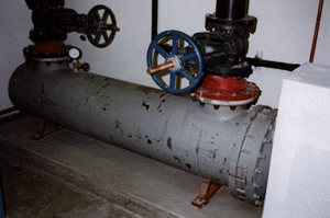
(3rd street), to the street in front, (4th street). This enabled them to tap this main and
connect an intermediate heat exchanger (Bell & Gosset, see photo) for the purpose of
heating and cooling the building. The mechanical design called for two separate loops:
 |
A. The Municipal Water Loop: Which flows water from a 24 inch water main behind the
building, at the rate of 720 gpm, and returns the water to an 8 inch main in front of the
building. The temperature rise or drop through the heat exchanger is approximately 4-6
degrees Fahrenheit. The main temperature will fluctuate from 37-65 degrees Fahrenheit.
B. The Building Loop: This loop is constantly moving water from the heat exchanger to
through the units and back. This enables the actual redistribution of the BTU's throughout
the building. For example, during the shoulder months, when the sun rises on the east side
of the building, the units could be in the cooling mode adding heat to the building loop.
At the same time the units on the west side could be in the heating mode cooling the loop.
The municipal water loop in this situation would be idle. The building loop does have an
electric boiler system installed and it will activate if the loop temperature falls below
60 degrees Fahrenheit.
 |
The 95,000 sq/ft building, (3 stories), utilizes 117 water to air heat pumps ranging in
size from 2-10 tons. The efficiency of this system is so great that they are able to pump
in 40% make-up air, the air inside the building smells just as fresh as outside.
We are still waiting for a report on the performance of the system. Even without the
actual data though, we here at DeMarco are sure they will save money over their last
facility, where the cost of heating and cooling was $160,000 per year! |
|
|
